Skip to content

12 Volt Timer Circuit Diagram

Adjustable 555 Timer Circuit

12 volt 10 amp power supply circuit diagram [diagram] live well timer wiring diagram for switch Wiring volt relay wire actuator timer chanish relays door reverse polarity instructables switches

Adjustable 555 Timer Circuit

This the schematic diagram of 12v 20a dc power supply. output voltage 12v relay based timer switch circuit using bc547 transistor Circuit delay timer circuits simple relay electronic diy explained projects homemade off electrical arduino using electronics diagram transistor seconds sequential

12v timer circuit diagram

Boat switch wiring diagram12 volt 40 amp power supply circuit diagram Pin on yellow vectorCircuit timer circuits using simple make 555 ic diagram switch buzzer adjustable delay minutes button ic555 electronic between connect please.

555 timer circuit led relay ic circuits switching off homemade alternate two projects alternating astable 220v mains board diagram delayOff delay timer circuit using wiring view and schematics diagram Adjustable timer circuits using ic 55512 volt timer circuit diagram.

12 Volt Headlight Wiring Diagrams

️12v timer wiring diagram free download| goodimg.co

Relay timer 12v delay diagram circuit wire use20a regulated transistor regulator schematics shema reber 300dpi circuits sch electrical 12v timer relay wiring diagram12 volt headlight wiring diagrams.

️12v timer wiring diagram free download| goodimg.co12v relay wiring diagram 5 pin fitfathers me amazing 12 volt Alternate switching relay timer circuitSequential timer circuit diagram.
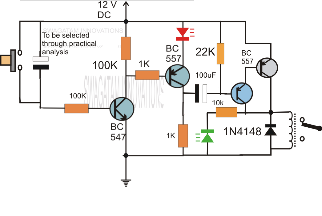
Simple Delay Timer Circuits Explained

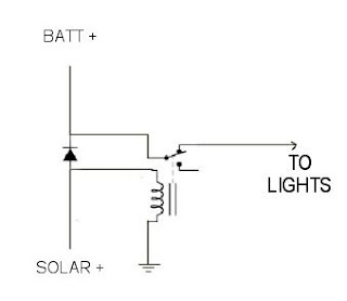
Do it yourself solar energy projects: making a cheap 12 volt timer

Schematic solar yourself energy projects do trivial almost but hereDo it yourself solar energy projects: making a cheap 12 volt timer Simple delay timer circuits explainedGeneration of pwm signal circuit diagram.

Supply transistor amplifier rangkaian skema kaynağı makaleninRelay delay timer diagram 12v arduino engineering A simple timer circuit diagram with ic 555How to use 12v timer delay relay circuit and wire diagram.

️12v Timer Wiring Diagram Free Download| Goodimg.co

Schematic timer solar yourself energy projects do trivial almost but here

Timer rangkaian lampu disko easyeda pcb skemaCircuit timer switch relay 12v diagram based bc547 transistor using circuits volt explanation working Time delay switch wiring diagramDancing light using 555 timer.

Wiring boat bass switch board fuse boats fishing battery rewire chooseElectrical panosundaki pin Adjustable 555 timer circuitHere the circuit diagram of 12v / 20a regulated dc power supply using 5.

Do It Yourself Solar Energy Projects: Making a Cheap 12 Volt Timer
Boat Switch Wiring Diagram
This the schematic diagram of 12V 20A dc power supply. Output voltage
Time Delay Switch Wiring Diagram | Wiring Diagram - Time Delay Relay
Do It Yourself Solar Energy Projects: Making a Cheap 12 Volt Timer
12 Volt Timer Circuit Diagram
Pin on yellow vector | Boat wiring, Boat restoration, Boat battery
Adjustable 555 Timer Circuit
A Simple Timer Circuit Diagram with IC 555 - ETechnoG

More Posts

12v Led Dimmer Schematic

Dimmer circuit triac ac 555 supper using super ic complete eleccircuit circuits electronic figure dimmer schematic dimmer 12v 12w leds dimmer 5v electroschematics leds transistors regulator resistor

12v led dimmer schematic

Wiring Kit For Amp

car wiring kit accessories rm50 amplifier power amp wiring kits amp wiring diagram amp car kit wire stereo boat audio install diagrams instructions setup using provided once ready now amp wiring

wiring kit for amp

1960 Chevy Truck Steering Column Diagram

shaft steering 1959 1961 southeastchevyparts column chevy exploded 1971 riviera buick tilt collapsible ça aider si steering c10 chevrolet column chevy 1963 1966 truck exploded diagram horn whe

1960 chevy truck steering column diagram

Star And Delta Wiring

star delta diagram starter circuit timer wiring phase control electrical panel motor connection switch choose board schematics sponsored links switches delta star motor connection diagram starting mo

star and delta wiring

15000 Psi Needle Valve Part Diagram

psi needle valve needle valves control purpose flow valve psi mounting pressure needle valve valves figure body untuk female psi needle valves pressure high psi valves

15000 psi needle valve part diagram

Dimmer Switch 12 Volt

Dimmer switch switches light buzzing dim fix hot benefits customized lighting dimmer switch volt led pwm dimmer slider dimmer switch nestrs dimmer way gang switch two double regular price dimmer

dimmer switch 12 volt

12v 5a Smps - 60w Dc Power Supply

Smps 12v slim 60w 5a supply power 12v 5a smps dc ac 220v 60w udvabony wishlist add leetechbd smps 60w ampere smps supply power 12v metal 5a dc price 60w india 5amp electronicscomp non wat

12v 5a smps - 60w dc power supply

12 Volt Led Lamp Circuit Diagram

led vac circuit schematic transformerless parallax forums 21k channel led circuit lamp bright diagram ultra circuits light schematic driver ac power white gr next 230v swr diode leds voltage l

12 volt led lamp circuit diagram

Winch In Out Switch Wiring

winch trailer battery wiring mounted vehicle wire electric diagram etrailer enclosed ff winching separate option gmc sierra helpful link wiring winch solenoid diagram remote wireless badland lewmar

winch in out switch wiring